Filters in electronics have the function of removing unnecessary frequencies from
signals with various frequencies and passing only the necessary frequency
signals.
Filters include passive filters that combine LCR components and active filters that
use operational amplifiers requiring power. Active filters have good performance,
but are difficult to design and adjust.
NF offers various types of active filters according to the purpose of use.
From this point forward, in order to understand the filter specifications and
selection method, we will first consider the ideal filter.
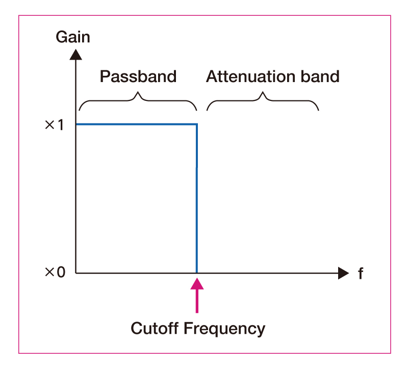
In addition, the passband and attenuation band switch at the cutoff frequency.
The characteristics of these ideal filters are illustrated in terms of frequency response.
Low-pass filter (LPF)
A signal with a frequency lower than the cutoff frequency passes
through.
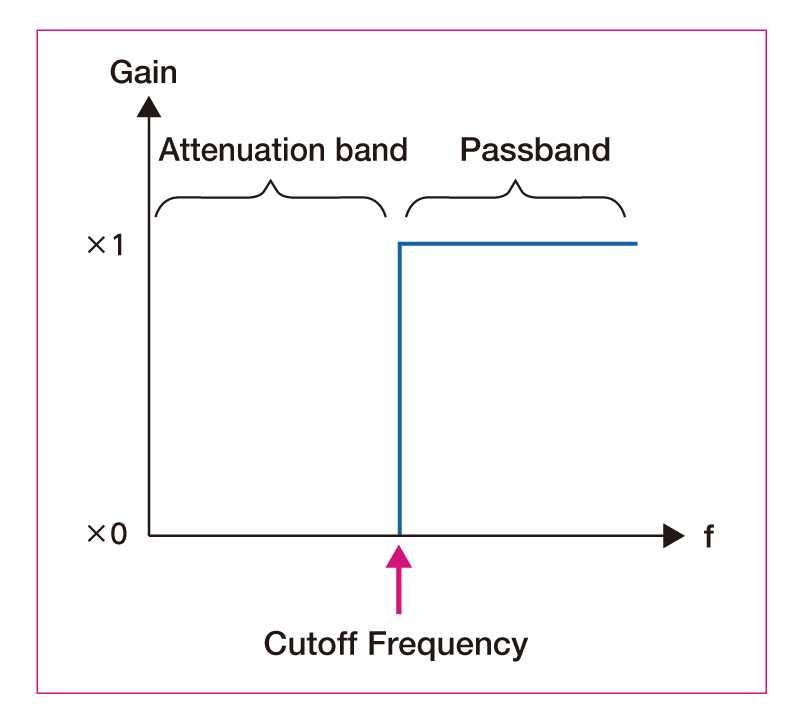
High-pass filter (HPF)
A signal with a frequency higher than the cutoff frequency passes
through.
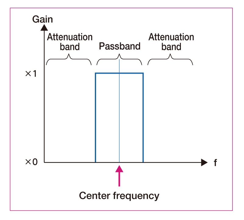
Band-pass filter (BPF)
Only signals near the center frequency are passed.
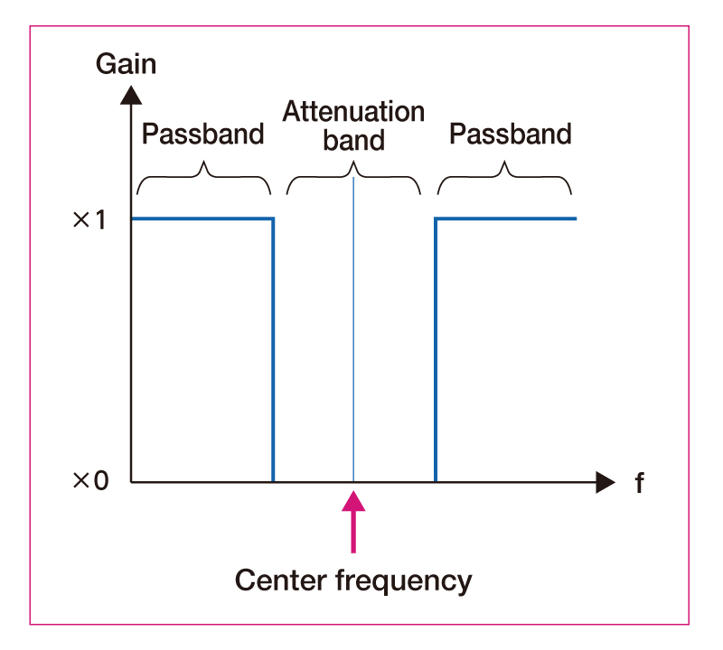
Band elimination filter (BEF)
Only the signals near the center frequency are removed.
It is difficult to actually realize the characteristics of an ideal filter.
There is terminology to describe the actual filter characteristics.
Frequency band of the signal passing through the filter
Frequency band of signal attenuated by the filter
The frequency band in the middle of changing from the passband to the attenuation band. It does not exist in the ideal filter, but it is present in the actual filter.
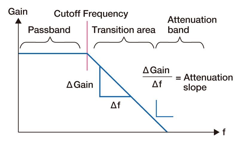
The frequency at the boundary between the pass band and the transition band.
The attenuation gradient is the value of the attenuation characteristic in the transition band. It is the amount of attenuation per unit frequency, and one octave (double the frequency) is often used as the unit frequency.
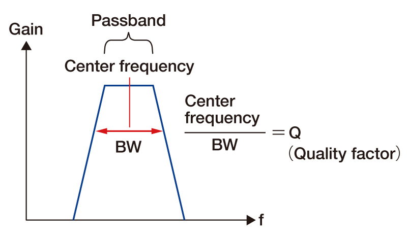
The frequency at the center of the passband of the BPF and the attenuation band of the BEF.
Q is a value indicating the sharpness of the characteristic in BPF or BEF. Divide the center frequency by the frequency bandwidth (BW).
A function for approximating the attenuation gradient. The higher the numeric order, the closer to the ideal characteristics.
Not all parameters can be the ideal filter. However, certain parameters can be
as close to ideal as possible.
Therefore, there are variations of filters with different characteristics.
The variations of the filters and their characteristics will be explained.
General filters with a good balance between circuit configuration and
performance
The pass band becomes flat (also known as MF: Maximum Flat)
Attenuation gradient is order x 6 dB / oct
Passband flatness required
Noise reduction in a frequency band different from the signal.
Processing of signals in which the frequency bands of the pass band and the
cutoff band are separated by 10 times or more.
The ringing and overshoot of the passing signal are small, and the rise time
is fast.
The delay time in the transition band is constant regardless of frequency
(also known as PL: Phase Linear).
Signals with a wide frequency in the attenuation band, such as music and
audio signals.
Requires good transient response characteristics.
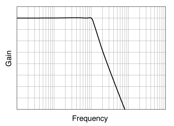
Ripple occurs in the pass band, but the attenuation gradient near the cutoff
frequency is steep.
Large ringing in transient response.
Attenuation gradient is steep with a continuous signal.
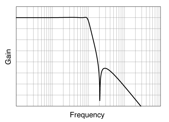
Ripple occurs in the pass band and attenuation band, but the attenuation
gradient near the cutoff frequency is very steep.
Large ringing in transient response.
Switch from the pass band to the attenuation band as close to the ideal filter as possible. (AD converter antialiasing, etc.)
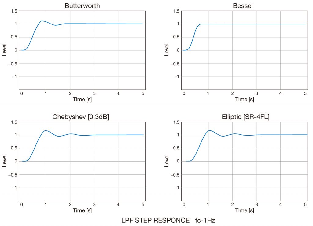
The steeper the attenuation slope, the greater the ringing.
This is due to the phase shift (difference in delay time) at each frequency.
If the attenuation gradient is gradual, the frequency delays of the signals
input to the filter will be equal.
This is expressed as having a linear phase with respect to frequency. Since
the phases of each frequency are output relatively aligned, the ringing of
the waveform is reduced.
However, the other filters except Bessel have a phase shift because the
phase change with respect to frequency is not linear. This causes overshoot
and ringing.
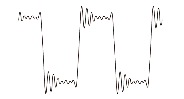
As a simulation of the filter characteristics with a linear phase change, a
square wave is created by adding harmonics up to the 17th order to the
fundamental wave.
"Then, the phases of the 13th, 15th, and 17th harmonics of this waveform
were changed.
This is a simulation of a filter that is not a phase straight line."
The overshoot is larger than that of the phase linear.
Phase linear filter
Square wave with harmonics up to the 17th order added
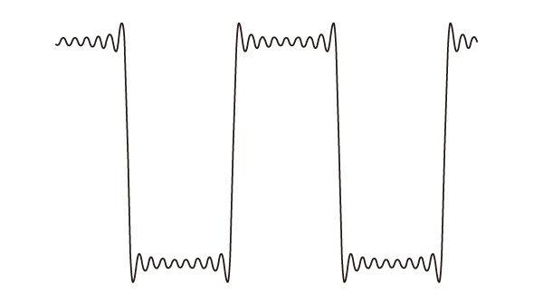
Non-phase linear filter
Square wave with changed phase of some harmonics
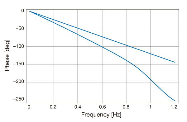
These characteristics were compared by frequency response.c
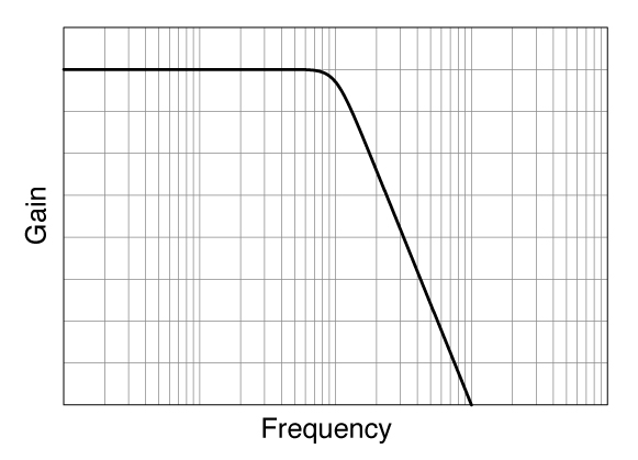
The line at the top of the graph is the characteristic of the bessel, and
the phase change is linear.
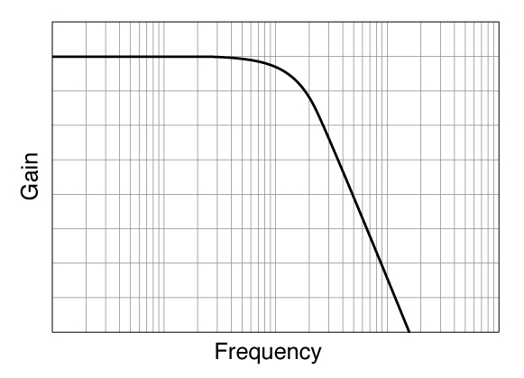
In the Chebyshev characteristic at the bottom of the graph, the phase change
is not linear.
These non-linear phase characteristics affect the rise of the signal
waveform.
■ Cutoff frequency can be set
The frequency can be set in 2 or 3 digits.
■ Filter characteristics can be set
LPF, HPF, BPF, BEF characteristics can be selected. The LPF can be selected from phase linear and maximum flatness.
■ Built-in preamplifier
Signal amplification can be done in conjuction with filtering
|
|
|
Recent post