- HOME
- > Product
- > Measurement Instruments
- > Impedance Analyzer
- > Impedance Analyzer ZA57630 : Product Information
Impedance Analyzer
Impedance Analyzer
ZA57630
"True Value"
Measuring true characteristics.
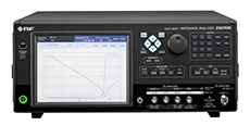
▲ ZA57630
![]()
For a broad range of impedance measurement requirements, from electronic parts and semi-conductor devices to material and substance characteristics assessments.
Basic accuracy
Measurement frequency
Measurement Impedance range
Measurement signal amplitude
DC bias
Measurement time
Measurement parameter
±0.08%
10 µHz to 36 MHz
10 µΩ to 100 GΩ
(Mode: IMPD-EXT)
0.01 mVrms to 3 Vrms
0.1 µArms to 60 mArms
−5 V to +5 V/−40 V to +40 V (more than 1 kHz)
100 mA to +100 mA
0.5 ms/point
Z, R, X, Y, G, B, Ls, Lp, Cs, Cp, Rs, Rp,
θz, θy, D, Dε,
Dµ, Q, V, I, εs, εs’, εs”,
µs,
µs’, µs”, FREQUENCY
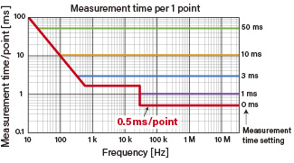
High speed measurement Industry fastest 0.5 ms/point
The fastest in the industry at 0.5 ms/point. Reduce takt time. In addition, by increasing the measurement time to be set, the measurement results are averaged and the influence of noise is reduced. The optimum measurement time can be selected as required.
Four measurement modes Able to handle a broad range of DUTs
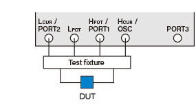
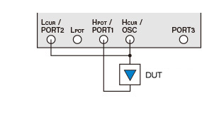
IMPD-3T
Default measurement mode
This mode provides high-accuracy measurements across a broad range of frequencies. Test leads and test fixtures can be used to suit test materials with a variety of different shapes.
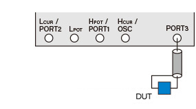
IMPD-2T
High-frequency measurement mode
This mode allows more stable measurements at high-frequency of 10 MHz or more. 2-terminal measurements using N connectors allows stable measurements even when using long cables.
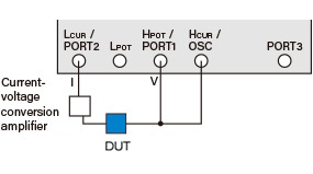
IMPD-EXT
Expanded measurement mode
Allows external amplifiers, shunt resistors or other devices to be connected. Allows measurements outside of the unit's specifications, like applying high voltages or detecting small voltages/currents.
G-PH
Gain/phase measurement mode
This mode provides measurements of transmission characteristics of devices like filters and amplifiers. Accurately measures the frequency response (gain, phase) when applying a sweep signal to the measured circuit.
Front panel Measurement connectors
