Driving the future of technology : Original solution in measurement and control
Driving the future of technology : Original solution in measurement and control
High Speed Bipolar Amplifier
High Speed Bipolar Amplifier
HSA SeriesHigh Speed, Broad Bandwidth, High Voltage Output
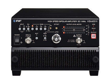
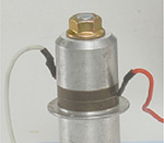
▲ HSA42011
In the test of electronic components and devices such as capacitors and coils,
it can stably drives the DUT that cannot be driven by other
amplifiers.
Used in advanced research fields such as medicine and
biotechnology.
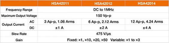
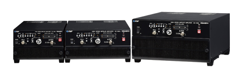
Line up
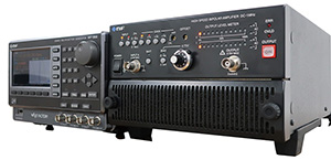
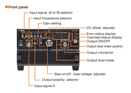
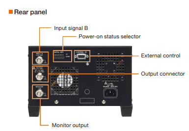
Front panel / Rear panel (HSA42011)
Stable output under various load conditions
Four-quadrant operation
The operation range of the HSA series is four quadrants as shown in the figure
on the right.
Current sources and sinks regardless of positive or negative
output voltage.
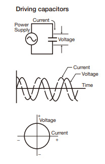
When an AC voltage is applied to a load including
capacitors and coils, current returns from the load.
In this case, a
typical AC power supply or amplifier may not be able to drive the load.
The
HSA series operates stably not only with capacitive loads such as a
piezoelectric element or solenoid but also with inductive loads because of its
4-quadrant output.
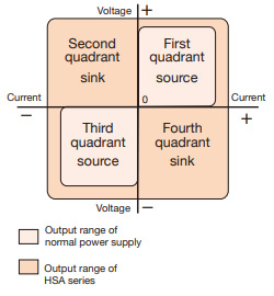
4-quadrant operation and Capacitive
When AC power is applied to a capacitor or inductor, the AC current of these
loads create a 90°phase difference with the applied AC voltage, but when the
instantaneous values of voltage and current are plotted on a 4-quadrant graph,
they pass through all four quadrants.
When applying alternating current to
capacitors and inductors in this way, a 4-quadrant operation is
necessary.
On the other hand, a general DC power supply can only be driven
in the first and third quadrants on the graph, therefore it is not suitable for
driving anything but resistive loads.
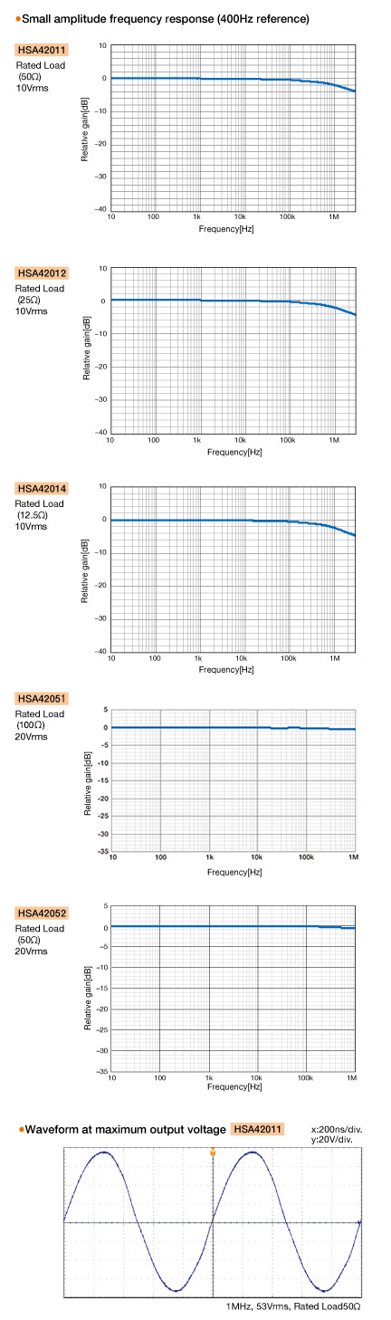
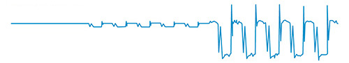
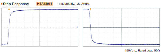
Fast response, wide frequency bandwidth, DC to 1MHz
High speed and high slew rate reproduce transient and repetitive operations with
good step response.
HSA series outputs AC and DC. Therefore, it is possible to
output positive/negative asymmetric signals or signals in which AC is superimposed
on DC.
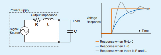
Low output impedance
Due to the output impedance of the power supply, the rise time of a capacitive or
inductive load is delayed.
The HSA series maintains a low output impedance over the entire frequency band,
suppresses voltage drop due to load, and operates at high speed.
Effect on Rise Time
In below figure, if the resistance of the output impedance of the power supply is R,
the inductance is L, and the load capacitance is C, the rise will be slow because
only R exists.
When L = 0, it takes C×R (seconds) to rise to about 60% of the final value
Convenient functions for various purposes
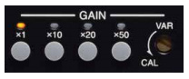
Gain setting
Set seamlessly by combining selectable fixed gain ×1,×10,×20,×50 and variable
gain x1 to x3 ( fine adjustment potentiometer)
With a gain ×1 setting, it is
used as a buffer amplifier that outputs at the same voltage as the external
signal generator setting.
Output polarity switching
With the [INVT] switch on front panel, an amplification can be selected which
the input and output phases are in the same or opposite polarity.
Balanced connection by two units of HSA series with output polarity set to
opposite, the output voltage and power are doubled.
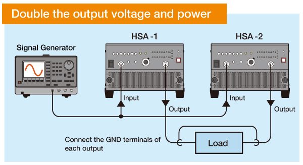
The output of the signal generator is divided and input to HSA −1 and. HSA −2
has a reverse phase output towards HSA −1.
And the load must be isolated from ground potentials and signal sources. And it
is also called BTL(Balanced Transformer Less) connection.
Output DC bias voltage setting
Superimpose a DC bias voltage (up to ±75V) on the output voltage.(Setting by
10-turn indicating dial)
As a test in which the DC voltage of the load fluctuates, it is possible to
superimpose the AC voltage on the DC voltage.
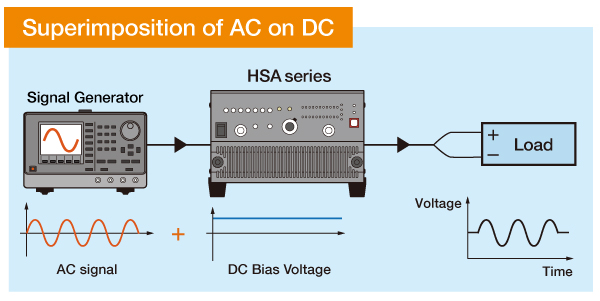
Set the rated DC voltage of the load with the DC bias of the HSA and superimpose
the AC voltage output from the signal generator.
It is also possible to sweep
the frequency of the AC output from the signal generator or superimpose it on
white noise.
Protection function
Function to protect the load from abnormal conditions.
Overload, overvoltage, internal power supply error, internal temperature error,
cooling fan error.
When an error is detected, the output is turned off or the overload protection
function is activated and the error LED lights up.
If the abnormal condition continues, the operation is disabled. (Only the power off
switch is effective)
Others
● External control
● Output on/off control
● Input A, B, A+B
● Input Impedance 50Ω/10kΩ selectable
● Output voltage monitor
● Power-on status setting
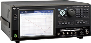
Frequency Response Data